

So … you’ve purchased a new digital to analogue converter. And there’s a button on the remote control, or perhaps on the unit itself, that lets you change the filter setting. With the press of a button you can switch between linear phase fast foll-off and low dispersion slow roll-off and hybrid and brick wall and NOS.
What on earth does any of that mean? Which should you choose? Is any one of them better than any of the others. Perhaps more to the point, is any one of those worse than any of the others?
And it’s not made any easier by different brands using different names for the same thing.
Well, we’re here to help, so let’s find out all you need to know – and perhaps some stuff you don’t need to know – about filters and what they do in a DAC. And, in the end, which one to choose
tl;dr
- The filter is the final step of converting PCM digital audio to analogue.
- It removes the jagged stair step pattern, restoring the waveform to a near perfect representation of the original analogue signal.
- There are several filter designs which can have an effect.
- One parameter of filter design is “Fast” or “Sharp” on the one hand, and “Slow” or “Smooth” on the other
- Fast/Sharp filters generally have the flattest, most extended treble response, yet are generally also the best at suppressing ultrasonic images from the final signal.
- Slow/Smooth filters generally have a high frequency response that starts rolling off earlier than Fast/Sharp, although around 20kHz (for CD-quality audio) the Fast/Sharp filters generally take over to greater effect.
- Slow/Smooth filters generally show less so-called ringing than Fast/Sharp when impulses are examined in an oscilloscope, but some do exhibit ultrasonic artefacts.
- Another parameter is “Linear Phase” compared to “Minimum Phase” or “Short Delay”. Where none of these three terms are mentioned, the parameter is most likely Linear Phase.
- Impulses delivered using Linear Phase filters tend to have the so-called ringing evenly distributed both before and after the impulse.
- Impulses delivered using Minimum Phase filters tend to have the so-called ringing all happening after them.
- Minimum Phase filters reduce latency – group delay in the signal. It is very useful in pro-audio applications.
- Linear Phase tends to be closer to the original input signal.
- Some DACs have variants with names like “Hybrid” or “Low Dispersion” which typically involve some compromise between Liner and Minimum Phase.
- Some DACs dispense with the filter entirely. These have various names, some of which disguise their character, but often they are called non-oversampling, or NOS.
- Their outputs are characterised by a rather diminished top octave and a considerable level of ultrasonic artefacts.
- But some audiophiles love their sound, and by golly they do exhibit an impressive impulse display on an oscilloscope.
What is a filter and why does a DAC need one?
Yes, first, we need to understand some basics. Here we’re talking only about PCM – Pulse Code Modulation – not Direct Stream Digital. DSD has its own interesting filtering (and other issues) which are not directly related.
So, to remind us all, PCM works by taking a sample of an analogue waveform at regular intervals and recording the sequence of numbers. In the overwhelming majority of consumer music, the samples are recorded in a 16-bit number space, which means it can have any value from -32,767 to +32,767. See in the following graphic. This is the waveform of a 1kHz sine wave I generated in an audio editing program:

The little squares on the line are the samples. The dialog box shows the actual value of one of the samples near the top of the curve. You can see that, horizontally, the squares – the samples – are evenly spaced. The horizontal axis is time. In this example I’ve used the CD-standard 44.1kHz sample rate. That is, the value of the analogue waveform is recorded 44,100 times every second.
So that’s what CD-standard PCM digital audio is: a sequence of numbers. It may be compressed into a FLAC file, CIRC-encoded into the pits and lands of an optical disc, or delivered in any of several other ways. But it is just a sequence of numbers. Of course, these days, there are higher resolution forms of PCM, but we’re going to stick with CD-standard to keep things manageable.
Now, let’s understand something clearly at the outset: in that waveform above, the curved line between the dots is a representation of the analogue wave that PCM is sampling. In the real-world signal, there may have been stuff happening in between those samples which has not been captured (that’s the justification for higher resolution formats). Any of the stuff that happened between the samples must have been due to frequencies higher than 22,050 hertz.
Now, the Nyquist–Shannon sampling theorem tells us if a bandwidth-limited signal is sampled at at least twice the rate of its bandwidth, the resulting digital stream can be converted back to analogue perfectly. (Of course, opinions on what is perfect may vary!)
Turning analogue waves into numbers
Now, we’re going to talk about how digital audio used to be created and subsequently decoded, back in the early days of the CD. Modern technology has changed much of this – for example, stuff is now routinely recorded in high resolution and converted to CD-standard digitally.
The first stage of analogue to digital conversion when the digital audio is being prepared is to employ a filter to cut out everything above the “Nyquist” frequency. That’s half the sampling frequency. If you don’t do that, some of the samples will be influenced by high frequency content that the PCM resolution simply cannot represent properly, and that will result in strange, unmusical artefacts in the recoding. Those artefacts are called aliases, so the filter is called an anti-aliasing filter.
So, in our CD case, a very steep low-pass filter – it lets the lower frequencies through but blocks the higher frequencies – kicks in at around 20,000 hertz. How steep? What exact shape? Who knows! That’s up to the people who made the analogue to digital converter.
The most important thing is to make sure that no significant content remains in the analogue signal before the ADC. Then the newly filtered waveform is run through the analogue to digital conversion process, and out the other side comes the sequence of numbers we’ve discussed.
Turning numbers back into analogue waves
Back in those early days, all digital to analogue converters – DACs – were so-called multibit converters. They used some form of resistor ladder to read the 16 bits of audio into discrete output voltages. This stream of discrete voltages then constituted the new analogue waveform. But it was a jagged one. Remember that space between samples? Well, with this system that space maintained the same output voltage as the sample, up until it was time for the next sample. So the waveform would be formed by all these little steps, 44,100 of them each second.
Here's an example of what this looks like. This is the output of an actual DAC I captured on an oscilloscope:

Monsieur Fourier’s mathematics assure us that these are formed by high frequency overtones. They can be eliminated by running the signal through another low-pass filter, called an anti-imaging filter. We’ll see why it’s called that later.
The effect of the anti-imaging filter was to eliminate those overtones and thus the step pattern. And so we had that “perfect” representation of the original signal, thus:
Of course, Nyquist-Shannon is talking theoretically. There were in fact imperfections. First there is some degree of approximation in 16-bit sampling. Contrary to what most think, this manifests as low-level noise. That’s why the theoretical noise floor of 16 bits is around -96dB, and of 24 bits is around -144dB.
One significant problem was that the resistor ladder had to use incredibly precise components. Another was that if you wanted the CD’s frequency response to hit 20,000 hertz, yet also have an effective anti-imaging filter, the filter had to be extremely sharp. In the analogue world, that manifests as generating significant phase shift.
Early digital “problems” and solutions
I was around and thoroughly into hifi when the CD was first launched in Australia. Indeed, I purchased the second Sony CDP-101 CD player – the inaugural model – sold in Canberra. And I did so love it. After years of vinyl noise, how great it was to have a source device which produced music with a background that was actually silent.
But pretty soon, though, there were objections from some in the high-fidelity community. They disliked the sound. Too edgy, harsh, unnatural and so on. Various fingers were pointed at things like the sharp anti-imaging filter, at 16/44.1 being too low in resolution (although some of those people praised the inaugural Philips player as sounding better … even though its DAC only ran at 14 bits.) There were many theories, including the use of LP masters to print CDs, rendering them too bright. (I recall one UK hi-fi magazine back then carrying an article in which the writer had recorded live using a Sony PCM-F1 ADC. He hated the sound, so he dubbed it to a Revox analogue tape, which fixed everything. Apparently.)
Whatever, time and technology moved on and the CD was assured of acceptance because it was more compact, more robust and more convenient.
And the electronics makers kept improving things. Oversampling was developed, which allowed the filtering to gentler. People kept improving the sound of CDs as recording engineers got used to the medium – witness the proliferation of remasters. And eventually delta-sigma modulation was developed.
That’s a highly mathematical subject, but in short the PCM gets converted to something like a Direct Stream Digital 1-bit stream prior to conversion to analogue. That kind of thing does convert more naturally. Since computer technology is now easily a thousand times faster and more capacious than it was then, what was hard in the early 1980s is easy now. So, the better-quality delta-sigma DAC chips come with a choice of filter modes, and it’s those that we’re digging into here.
Let’s see what some filters do
We can measure the differences between filters. Better yet, we can show these things with images of waveforms and various measurements. In order to capture these, I used the Topping E30 DAC, a low cost, high performance unit which offers you a choice from six filter models. Quite a few DACs now have user-selectable filter profiles. As does, for example, the Astell&Kern @Futura SE200 digital audio player. I’ve measured the output of several such devices in recent years.
What I’ve found is three main differences produced by the different filter options:
- Different treatment in the high frequency response;
- Differences in the amount and timing of any ringing in impulse response; and
- Differences in the generation of unwanted ultrasonic noise or artefacts.
Frequency response
Here’s what Topping calls its six filters:

Let’s start with the frequency response:

As you can see, Filters 1, 3 and 6 were the same, maintaining the level all the way out to 20kHz – down by just 0.1dB – and then falling away rapidly. This is fairly representative of the actions of filters called “Sharp Roll-off” or “Fast Roll-Off”. Basically, these prioritise a flat frequency response (and, as we’ll see, reduced ultrasonic artefacts). Filters 2 and 4 start rolling off earlier, down by nearly 0.1dB at 10kHz, 3dB at around 17kHz and -5dB by the time it gets to 20kHz. These have names like “Slow Roll-off” and “Smooth Roll-off”.
At this point I will note that a lot of reviewers profess to prefer the sound from this Slow/Smooth kind of filter.
Standing by itself is Filter 5. This turns out to be a rather special one. As you can see this rolls off even earlier, but in the end not as sharply as either of the other two. It’s down by around 0.7dB at 10kHz and -3dB at around 19kHz. Hello, hello, what have we here? What’s that slight uptick just to the right of 20kHz? Let’s change the horizontal scale from logarithmic to linear:

Now we can see it a bit more clearly. Yes, there’s a definite uptick just above 20,000 hertz. What’s all that about? Wouldn’t any typical filter keep the curve heading down? Don’t worry. We will solve this mystery.
On an impulse
Before getting further into that mystery, let’s check out how the six filters deal with an impulse signal. An impulse is an extremely rapid change of signal level. Think a cymbal strike. Sometimes the subjective words used to describe it are things like “attack” and “speed”. Being the reductionist that I am, I reduced the impulse to the most impulsive possible signal. I made an audio file one second in length that was complete digital black – which is to say all the samples were at zero. Except for one. That one sample was at -3dB FS (that is, 3dB down from the maximum.) And to increase the rise time even more, I strayed briefly from my commitment to 44.1kHz and did this one with 192kHz sampling. I fed this test signal to the Topping E30 with each of the six filters selected in turn and captured the resulting output on an oscilloscope. Here’s the output for the F1 – Sharp Roll-off filter – selection:
There’s the impulse in the middle, with an approximately symmetrical ripple – or “ringing” as it’s often called – to the left and right of the impulse. Somehow the impulse is making waves, so to speak, before it even arrives! Next is the F2, Slow Roll-off filter:

It’s like the first one, but with far less fore and aft ripple/ringing. It’s almost as though the steeper filter may have reduced the high frequency artefacts in the signal. We come to F3, Short-delay Sharp Roll-off:

Now this is different. There is no ripple leading up to the impulse, it’s all afterwards. And if you compare the height of the ripples, it looks like those before and after in F1 have been added together into the new after ripples in F3. So, same overall ripple, but just in a different place. Presumably this has something to do with “Short-delay”. In some other brands of device, what you see in F1 and F2 is called “Linear phase” and in F3 (and F4, as we’ll see) is called “Minimum phase”. The “Minimum” refers to latency. In Pro audio, latency is a problem. If a singer is being recorded, while listening over headphones to the backing track, if the backing is delayed in their headphones, they will not be in time. “Minimum phase” doesn’t really mean reduced phase errors, but reduced overall or “group delay”.
So let’s see F4, Short-delay Slow Roll-off:

It’s like the difference between F1 and F3: the pre-“ringing” has been shifted to post-“ringing”, adding to the existing “ringing”. But you have to admit, that’s a mighty nice-looking impulse. (We’ll see later why I put “ringing” in scare quotes.)
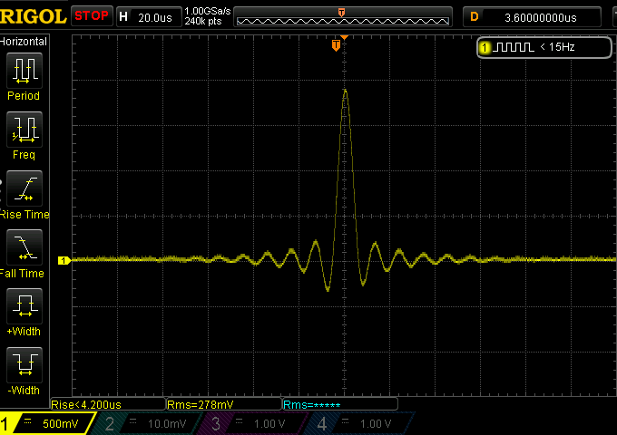
And that brings us to F5, Super Slow Roll-off:

Now, isn’t that one incredibly sharp impulse? And look, there is no ringing or ripple on either side. If you were really picky, you might note that it leans a little to the right and the end of the impulse doesn’t hit zero at quite as sharp an angle as it left it a few microseconds earlier. Against that, note that the impulse is significantly higher than each of the others. And the rise time of less than 3.2 microseconds beats the less than 4.2 microseconds of the next best.
For completeness, here’s F6, Low Dispersion Short Delay:

Note the extended frequency response of this one up above? The impulse looks like it’s a compromise between F1 (sometimes called Linear Phase) and F3 (Short-delay or Minimum phase), with less pre-ripple and more post.
Which would you pick?
Perhaps you won’t be surprised to read that many high-end audio reviewers incline towards Filter 5 in their subjective listening. I am basing this not on reviews of the E30, of which I have read none (apart from my own, published elsewhere) but on their reviews of a very different breed of DAC, which uses a quite different technology. Again, we’ll return to that.
It is tempting to choose Filter 5. That impulse certainly is sharp. That pre and post ripple is certainly absent. There is a frequency response trade-off in the top audible octave, as we’ve shown. But isn’t that more than made up for in a sharp attack?
Okay, let me cut to the chase. I always choose F1, or the equivalent in other DACs. One reason is the extended frequency response, but here’s another reason:

This is a screenshot of the test signal that I generated for this test, zoomed in close. This is the source signal. As you can see, all the samples are at zero except for the single displaced sample, which is at -3dB. Now, look at that thin line joining the dots. That wobbly thin line is generated by the software I used to create the test. It is the single mathematically valid smooth line with which the dots can be joined. It is a good representation of the soundwaves that would be created in the air should that signal be perfectly delivered into the air.
And which of the above impulses does it most closely match? No, not the Short-delay/Minimum Phase ones, which shift the ripple to the right. No, not the Slow Roll-off ones, which reduce the level of the ripple.
And no, not F5 which, naively, looks like the best.
The one it matches rather closely is the first filter, Sharp Roll-off, called in some other equipment (Cirrus Logic and ESS, for example) Fast Roll-off Linear Phase.
Now let me be very clear about this. Those ripples are simply not audible. They are necessary artefacts of the fact that the sound is bandwidth limited. And it is not being bandwidth limited by your DAC, but was bandwidth-limited when the signal was originally digitised. The ripple you see in the output was there immediately after the filter right near the start of the process. “Ringing” is an alarming word, but in this context it is nothing that you can hear.
Time for some shocking pictures
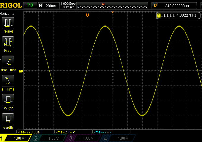
Nope, not that kind of shocking picture. Just some rather revealing waveforms and graphs showing what different filters do. So, let’s look at a pure, digitally generated 1.002kHz waveform delivered by the Topping E30 (why 1002Hz? I’ve been using this instead of 1kHz for many years, for reasons that no longer make sense to me, but I keep using it for comparability with my previous measurements.) This was captured on the oscilloscope:

That’s using Filter 1. But the picture was the same with F2, F3, F4 and F6, so there is no point in repeating them. And they all look, well, perfect.
Now let me show you two more outputs captured on the same oscilloscope with the same input signal (but with different output levels and different vertical scaling):


The first one of those was from the one of the filters on the $270-ish Topping E30, while the other was the only output available from the $12K+ Aqua La Scala MKII Optologic DAC, which I measured in 2020. The F5 filter is described by Topping as “Super-slow Roll-off”. But it’s known also as “Optimised Transient” (in a Pro-Ject Audio DAC) and zero oversampling, or NOS, for non-oversampling. This is kind of a reversion to the earliest Sony-style resistor ladder digital-to-analogue conversion I described earlier. But not a full reversion … because the output filter has been omitted. That’s why you see that jagged step-pattern in the 1kHz sine wave.
Of course, that step pattern just gets worse as you go up in frequency. A 10kHz sine wave is only defined by four or five (literally one or the other) samples in each cycle. You can imagine how that looks on the oscilloscope when it is delivered unfiltered. So here’s the output from the Topping E30 with the F1 filter – Super-slow Roll-off” – engaged:

But if you do filter the output, things become “perfect” again. Here’s 10kHz from Topping E30 with F1, Linear Phase Fast Roll-off:

For completeness, here’s the 10kHz output from the Aqua La Scala (sorry, I forgot to press the button on the oscilloscope to stabilise the waveform – it being beyond the capacity of the oscilloscope to manage it itself, given the variation – but you get the picture):

Let’s call those unfiltered outputs NOS from now on, that being the most common term. The images above show the uncertain nature in NOS outputs are resolved.
Let’s look at this in a different way
The problem with the software I mostly use to measure stuff is that the PCM sample rate of the measurement has to match that of the input signal. So if you want to see what might happen in the ultrasonic when something is fed a 44.1kHz signal, it won’t help. Well, except for intriguing upticks in frequency response output at the extreme right of the graph as shown above.
So I figured I’d try something different: send a white noise signal through the DAC at 44.1kHz sampling, and record it with another computer at an extremely high sampling rate. Note, white noise is not representative of music because all frequencies are present at roughly the same level. With music – with the real world, really, the level tends to fall away at around 6dB per octave. Anyway, as a point of comparison, here’s the spectrum of the input signal I used:

And here’s how it looks at the output of the Topping E30 with Filter 1 selected, sampled at 192kHz:

As you can see, and as expected, a flat response out to around 20kHz and then an extremely sharp drop-off. The result was identical with F3 and F6.
And here’s the Slow Roll-off response, also matching what we’d expect:

Or is it what we’d expect? It looks like the output is only down by around 12dB at the Nyquist frequency – that’s 22,050 hertz. Which means there’s a surprising amount of … something or other coming out of the signal that’s higher in frequency than what a CD-standard PCM stream is supposed to be able to carry.
And, now, the big reveal. Here’s the F5, Super Slow Roll-off, NOS output:

What. On. Earth. Is. That?
Well, funnily enough, when you don’t filter the output of a stairstep signal, you get lots and lots and lots of ultra-high frequency spurious noise. Well, it’s not entirely spurious, as we’ll see in a second. It’s a series of “images”, thus the description of the filter as “anti-imaging”.
(See, I said we’d resolve these mysteries!)
Again, that’s a horizontally logarithmic view, which is useful in most circumstances. But switching to linear discloses a little more detail:

All that stuff beyond 20,000 hertz is not real signal. They are just weird mathematical artefacts resulting from not filtering material which was intended from the outset to be filtered at the output. I am emphasising this point because, for example, when I was writing about that super-expensive Aqua La Scala DAC, I queried the company with my measurements and it responded: “La Scala DAC does not filter or alter the original samples of the musical program: they are converted to analog domain without modifications. In this way we also avoid the “intersample overs” problem that is vital to faithful reproduction, considering current recording studio practices. With our R2R conversion technology the sound is natural, fast, dynamic, and without the sense of compression characterizing others converters.”
Ohhhh-kay, I guess. That “intersample overs” could be a problem with some content if a simple upsample is conducted without simultaneously increasing the bit depth, providing some of that increase as headroom.
The fact is, R2R still requires high precision resistors. It was bad enough trying to manage this for 16 bits. With 24 bits, the precision required goes from ridiculously high to impossibly high. Which is why the noise performance of the La Scala with 24-bit audio was slightly worse than that of the Topping E30 with 16-bit audio. And it results in high frequency artefacts – images – which, on that white noise test are merely 12dB lower in level than the actual content. Fortunately they peak at 60kHz, which your tweeters will barely, if at all, reproduce.
But, said one prominent reviewer 15 years ago in an argument suggesting NOS DACs were best:
What about the ultrasonic energy present at the output of a zero oversampling DAC? Is it likely to overload or generate distortion products in the associated analog chain? While that is always a possibility with high-frequency test signals, there is no evidence that this is at all an issue with music program material. The proof is in the listening.
Well, I was definitely using artificial test signals – white noise -- earlier. And, I should add, I generated that white noise in the digital domain, so it hadn’t had the benefit of anti-aliasing filtering. So perhaps he’s right and all this stuff isn’t relevant with real music.
Filters and real music
Which meant, of course, I had to test some real music. I grabbed twenty seconds of Dire Straits’ “Money for Nothing” and played it through the Topping E30 with my preferred F1 filter, and again with the Slow F2 filter and yet again with what I’m now going to call F5: NOS. This time I used 384kHz sampling on the recording computer to see what was happening quite a long way into the ultrasonic frequencies.
Note, there are none of the problems with this that might exist with the white noise. Admittedly, this was one of the earliest pop rock digital recordings, but it was properly produced and filtered prior to PCM encoding. And it’s real music. Here’s F1 from the Topping E30, Linear-phase Sharp Roll-off:

As you’d expect – or at least, hope for – a sharp drop-off there. That vertical line is spot on 20kHz. That stuff to the right, where something-or-other rises to around -72dB? First, I’ve offset the scale by 40dB to keep everything in the picture. So that rise is to around -112dB. That’s noise inherent in the Delta-Sigma processing of both the Topping DAC, and the analogue to digital conversion of my RME ADI-2 PRO FS R Black Edition with which I was measuring all this stuff. You may be troubled by such noise … if your tweeters can deliver 180kHz signals at -112dB.
Next is the Slow F2 filter:

How’s that for weird! Just below 20kHz the response is a little lower than with the F1 filter, as the frequency response graph would make you expect, and then the drop is precipitous. But at around 23.7kHz, as finely as the course grain of my software will disclose, the output goes shooting up again. This is a poorly suppressed mirror image of the high frequency component of the real signal, reflected into the ultrasonic range. The midpoint between the real signal and the artefactual image – the mirror doing the reflection if you like – is at 22,050 hertz, the Nyquist frequency. Fortunately, the slow-acting filter really kicks in more intensively around 28kHz and kills of the rest of the image.
Now, let’s check it out with the F5/NOS “filter” selected:

Okay. This is real music and the output is exhibiting real ultrasonic artefacts at significant levels. There’s a lot going on in that space above 20kHz. So here’s the same result, but this time with the horizontal scale linear rather than logarithmic:
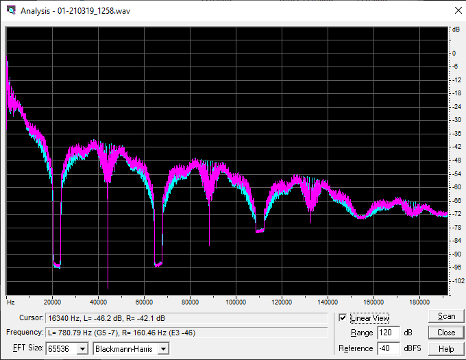
Now we see why the filter lacking in NOS DACs is called “anti-imaging”. Clearly the 22-ish kHz to 42-ish region of this graph is a reversed representation of the actual signal, albeit at a lower level. And the 43-ish to 63-ish section is a non-reversed section of the original signal, again albeit at an even lower level. And so on, and on, and on, and on, and on, and on and …
I’m guessing that this might be an issue with “music program material”.
What does all this mean?
Let me make very clear: I do not intend the various measurements I’ve shown above to suggest that you can actually hear the “images” produced by NOS DAC designs. Indeed, I thought the Aqua La Scala amp delivered a fine signal, as far as my ears could tell. I’m quite confident that it would have produced the images demonstrated using the NOS filter on the Topping.
But what did various reviewers hear with the La Scala?
- Music positively bursts into life. For the sinister jazz and macabre vocals that dominate Angelo Badalamenti’s score for Twin Peaks: Fire Walk With Me, we hear more deeply etched player outlines delivered with nary a hint of rigidity. The all-important sense of effortless is maintained, especially with microRendu in play.
- Put primitively, if out of 100 transparency points, one applied 80 to the source, 20 to the integrated amp and 0 to the speakers, the shiniest most capable new DAC wouldn't really shine. Anyone upgrading from MkII to MkII Optologic must insure that the associated hardware is translucent enough to upstream improvements. Now the increased visibility of recorded space—that often subtle domain of gossamer reflections/reverb—and its influence on sophisticated tone with more generous decays will be obvious and well worth the conversion fee … [and so it goes for another 150 incomprehensible words. But I think he likes it.]
- The already extraordinary sound quality of this icon is now improved in every aspect: time coherence, microdynamics, timbre, and without losing that magic atmosphere for which La Scala is widely renowned.
And so on. As for me, I reckon that the Topping E30 set to Filter 1 permits music to positively burst into life, provides a hundred transparency points, and delivers time coherence, microdynamics and timbre in abundance. Again, as far as I can tell.
As I mentioned above, reviewers who claim an ability to hear the effects of different filter settings typically prefer “slow” filters. If they can indeed hear their effect, it is presumably because they find the earlier, steeper roll-off of the top octave more pleasing to their ears. That may explain the particular applause often given to NOS DACs.
Even one of our own brands has perhaps been partially seduced by this NOS applause. The Astell&Kern &Futura SE200 digital audio player defaults to “Super Slow Roll-off” – which is NOS – for it’s AK DAC output.

Fortunately, you can just go into settings and change that to “Sharp Roll-off” for the ideal settings.
Another decent budget DAC is the Pro-Ject Pre Box S2 Digital, which uses dual ESS9038Q2M DAC chips. These chips have seven filter selections, none of them NOS. Yet Pro-Ject has added its own eighth filter option, which it recommends should be used. It calls this one “Optimal Transient”, but it is just another filterless NOS output.
So, which filter should you choose?
That, after all, is where we started.
Let me clear. I do not really know what “microdynamics” are. I’ve been intrigued with high fidelity by almost half a century, but remain innocent of an understanding what an “etched player” might sound like, and what “rigidity” is in regard to sound quality. I do like “gossamer” as a word, but I don’t really understand how it relates to sound reproduction. However, I do have some sympathy with “magic”.
As always, if your equipment has options, play with them and see what you like. But if you want what is clearly the most technically accurate – that is, high fidelity – output from your DAC, choose fast roll-off or sharp-roll-off, and linear phase (or no named phase) rather than minimal phase.
And do not choose NOS or Optimal Transient or Super Slow Roll-off. They are objectively worse, although it seems plenty of people are able to imagine them to be subjectively better.


